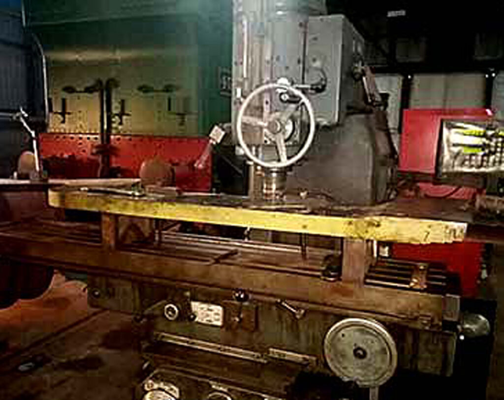
Having reduced the thickness of the extension frame plates where needed they were then set up flat on the milling machine table to create a curved profile where the thickness had been changed. This can just be seen above the lower handwheel. The machine spindle below the upper handwheel is fitted with a profiled milling cutter to generate the shape required.
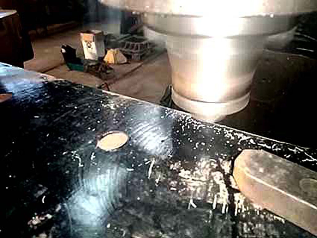
This photograph shows the profile milling cutter in action during the early stages of this machining.
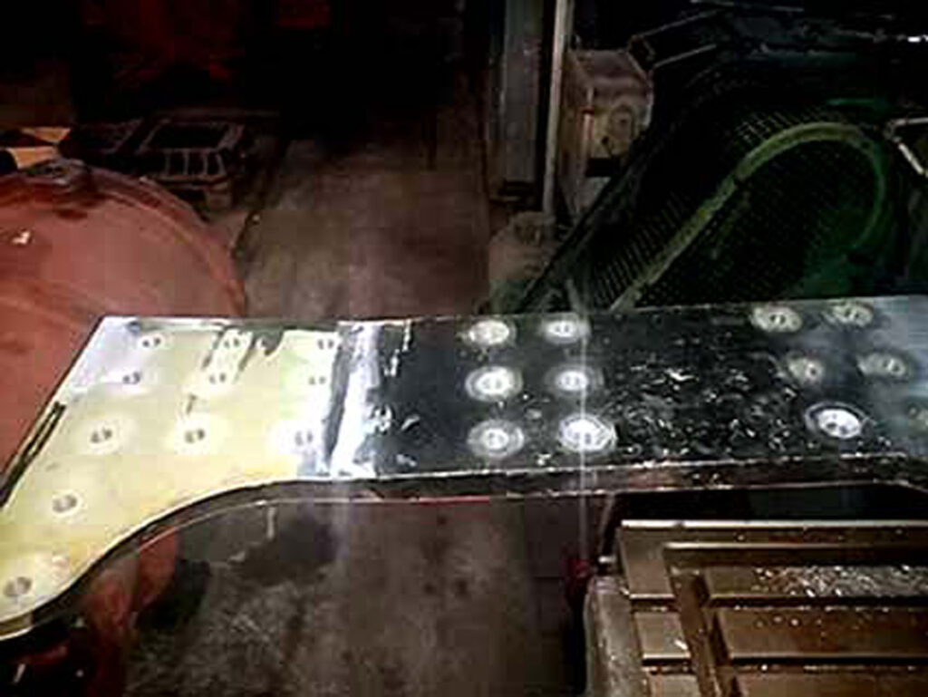
Having completed the shaping of the extension frame plates the next step was to drill each plate ready for where the 4561’s front buffer beam and leading pony truck frame stretcher will be fitted.
The 8 holes on the left will be used for the buffer beam angles and the 11 holes centre and right are for the stretcher.
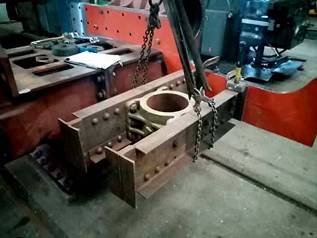
The all new pony truck stretcher is tried in position against one of the extension frame plates fitted to the cylinder block to confirm alignment and dimensions are to drawing. The team has fabricated the stretcher from a central casting bolted into an assembly of steel plates and angles riveted and/or welded together. The frame plate mating faces have been machined to ensure a good fit between the 2 extension frame plates to ensure they are supported the correct distance apart.
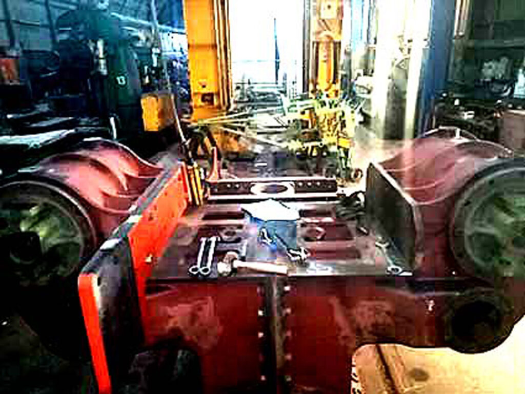
This photo shows the assembly so far from the rear. It also shows the new rear cylinder covers in position on each cylinder.
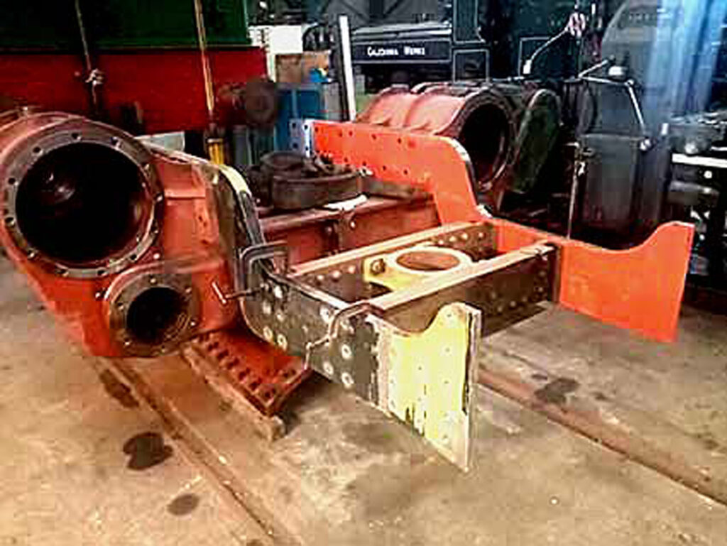
The next stage was to fit the second extension frame plate in place as seen in the next photo. when the whole assembly of cylinder block, extension frames and truck stretcher was being checked to ensure all dimensions and alignment were correct.
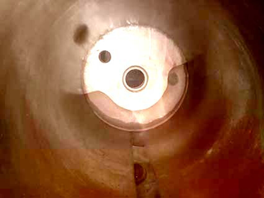
A lockdown challenge for you:
This photo is taken from the front through one cylinder and shows the rear cover in position at the back. The central hole is where the piston rod will go. Bearing in mind that the cylinder block assembly is upside down what are the two holes to the left of the piston rod for – one in the back cover, the other in the cylinder wall?
First published on the WSRA 4561 restoration blog.